What is the long range RFID antenna
RFID long range Antennas are essential components of a long range RFID system because they convert the UHF RFID tag 's signal into RF waves that can be detect by long range RFID reader .
Long range RFID antennas, unlike long range UHF RFID readers, are powered directly by the RFID reader. When the RFID reader's energy is transmitted to the RFID antenna, the RFID antenna generates an RF field, which is then used to transmit an RF signal to the RFID tags in the vicinity. The RFID antenna's gain is the efficiency with which it generates waves in a particular direction. Simply put, the greater the gain, the more powerful and far-reaching the RF field of an antenna.
The RFID antenna's polarity is defined as whether the RFID antenna emits UHF RFID waves along a horizontal or vertical plane. The RF field is described as horizontally linear if it is a horizontal plane, and the same principle applies to an RFID antenna that creates a vertical plane.
The polarity of a UHF long range RFID antenna can significantly affect the read range of a system. The key to maximizing read range is to ensure that the polarity of the antenna matches that of the RFID tag. If these do not match, for example, a vertical linearly polarized antenna and a tag with a horizontal linearly polarized antenna, the read range is severely limited.
A circularly polarized antenna transmits waves that continuously rotate between horizontal and vertical planes, allowing RFID tags to be read in multiple orientations. However, because the energy is divided between two planes, the read range of a circularly polarized antenna is shorter than that of a linear antenna with a similar gain.
What factors should you consider while selecting a long range RFID antenna?
Any RFID system must include a long-range RFID antenna. Unless the RFID antenna is built into an integrated long-range RFID reader, you'll have to choose and buy the proper long-range RFID antenna for your needs. And there are numerous possibilities to choose from.
Gain has an impact on the read range and beamwidth. Higher gain RFID antennas provide a longer scan range but a narrower beam. Low-gain RFID reader antennas offer a shorter read range and a broader beamwidth. Antenna gain should be chosen according to the shape of your interrogation zone and your coverage requirements. The most frequent gain is 6 dBi and 12 dBi for RFID antennas, however, you may also find RFID antennas with 1 dBi (low gain) and 11 dBi (high gain).
The ratio of two powers is measured in decibels (dB), which is a logarithmic unit of measurement. Gain can be stated in a variety of quantities, including dB, dBi, dBd, dBm, and dBW, making it a little more difficult to quantify. Which two ratios are being measured is determined by the difference in the unit conveyed (dB, dBi, etc.). It's impossible to compare antenna gains in two different units of measurement.
dB–The antenna’s power output is measured against the power input into the antenna.
dBm–The antenna’s power output measured against 1 milliwatt of power
dBW–The antenna’s power output measured against 1 Watt of power.
dBi–Antenna gain expressed in dBi and is basically the measurement of the amount of power required to produce a certain field of electromagnetic waves in comparison to a “perfect” (no loss, isotropic) antenna’s ability to produce the same field. (dBi = dBd + 2.15)
dBd–The antenna’s power output is measured against the gain of a halfwave dipole antenna.
The key takeaway is to figure out how much read range you'll need to meet your application's requirements. Be sure to account for antenna gain and compare antenna gains with similar units of measurement.
long range UHF RFID antennas, like long range UHF RFID readers and long range RFID tags, are intended to operate within certain frequency bands. RFID Antennas cannot send or receive information from the RFID reader or the RFID tag unless they are adjusted to a specified frequency range. The majority of long range RFID antennas operate in one of the following operating zones:
(902–928 MHz) US or FCC
ETSI or EU (865–868 MHz)
860–960 MHz (global)
For applications that run in many countries or will be assessed in both the United States and Europe, the Global operating region is an excellent "catch-all." Otherwise, a smaller frequency range RFID antenna is preferable; it will provide greater performance and, all things being equal, a longer read range. It's worth noting that, in order to communicate successfully, all RFID equipment within a system must be tuned to the same frequency range.
Double-check the frequency guide published by GS1 to determine whether frequency or operating region is appropriate for an application, and make sure that all pieces of the RFID system (RFID tags, RFID reader, and RFID antenna) are compatible within the country in which they are running.
The key takeaway is to double-check the frequency guide for each country's specific requirements if the system will be operating somewhere other than the United States or Europe. If the exact restrictions aren't established, a universal frequency range antenna is a good choice.
You can choose between circular and linear polarization antennas for polarization. The read range of circularly polarized antennas is shorter, but they are less orientation sensitive. Right-hand circularly polarized antennas (RHCP) and left-hand circularly polarized antennas (LHCP) are available (LHCP). Dual circularly polarized antennas with both left and right polarization are occasionally seen. Read-only tags with antennas parallel to the plane of the wave will benefit from linearly polarized antennas since they have a longer read range and a more focused beam. If your tag orientation isn't stable, choose a circularly polarized antenna, especially if you're employing single dipole tag antennae.
The axial ratio is the ratio of orthogonal components of an E-field. A circularly polarized field is made up of two orthogonal E-field components of equal amplitude, which are 90 degrees out of phase. Because these components are of equal magnitude, the axial ratio is 1 or 0 dB. Axial ratios are often specified for circularly polarized antennas. The axial ratio tends to degrade away from the main beam of an antenna, therefore, in the spec sheet for an antenna, you can sometimes see information such as: “Axial Ratio: <3 dB for +-30 degrees from the main beam”. This indicates that the deviation from circular polarization is less than 3 dB over the specified angular range.
Beamwidth is directly related to gain and is the width of the beam or RF field, as the name implies. There are two fields: azimuth and elevation, and each have a beamwidth that is important for determining where the RF waves will be focused. Linearly polarized antennas have a small beamwidth in one field and a beamwidth of 30 degrees to 360 degrees in the other, depending on the gain. Because the antenna may be physically spun 90 degrees to exhibit the opposite beamwidth, most linear antenna specifications mention the elevation and azimuth beamwidths as the same degree.
In general, the smaller the beamwidth, the larger the gain. Most users must choose between a longer read length with a small breadth and a shorter read length with a wider RF field for their application. A few instances are shown below. Manufacturers' drawings of 2D and 3D radiation graphs provide a "map" of the RF field produced by the antenna. These maps are quite useful when selecting an antenna for a particular application. Two images will be used in 2D radiation graphs: one for the horizontal or azimuth plane and one for the vertical or elevation plane. In all fields, 3D radiation graphs provide a 3D mapped image of the exact beam pattern. The most important takeaway: An antenna with a broad beamwidth has a lower gain and covers more area vertically or horizontally (or both), whereas one with a narrow beamwidth has a greater gain and reads farther but covers a smaller area.
this will be determined by the operating country and will only influence the UHF frequency. As you may be aware, the frequency bands for UHF RFID in the United States, Europe, and other locations range slightly according to legislation. The majority of UHF antennas are designated as global and tuned for frequencies between 860 and 960 MHz. Long-range RFID antennas can also be found that are adjusted individually for each region, somewhat improving their performance in that area. In Europe, for example, an 865-868 MHz antenna will perform better than a worldwide antenna, however, this may not be discernible in most applications. The global RFID antenna will work well for most applications; however, for tough deployments (long read ranges, RF challenging environment) or when global is not accessible, you can choose a region-specific antenna.
 Source from google
within the same frequency, smaller RFID antennas have a shorter read range and vice versa. Near Field Antennas, which use near field rather than far-field like standard UHF long range RFID antennas, will have the least read range for UHF technology. These are frequently used for item tracking and in situations where small ranges are necessary for item singulation and/or security.
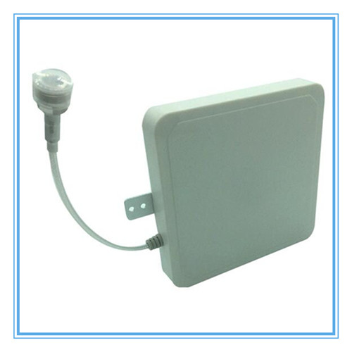
If you're tight on space or want to be more aesthetically pleasing, search for low-profile antennas with a side connector or pigtail.
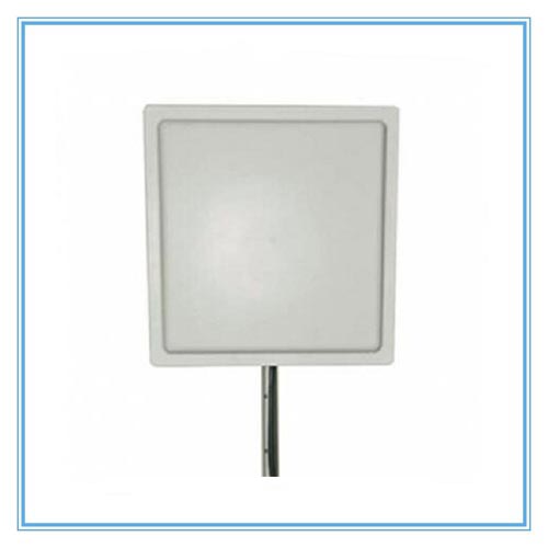
Long-range RFID antennas can be as small as a cell phone and as huge as a television. The read range is usually determined by the antenna size: the larger the antenna, the higher the gain, and the longer the read range, and vice versa. However, because they were designed for a specific application, some antennas are exceptions to the norm.
Because some applications do not allow for much available space in the region where the antenna will be mounted, size limits may play a role in the decision-making process. Certain settings, such as retail businesses, may not have the space or aesthetics to accommodate a massive 15 x 15-inch antenna. Small antennas are best for reading and writing at the item level, as well as applications that demand narrower read zones, such as conveyor belt reading and staff access control. The RFID antenna's size should be determined by the amount of space available in the application area. Also keep in mind that the shorter the read range, the smaller the antenna.
voltage standing wave ratio or also called return loss - Due to mismatches in impedance within the connector, some of the signals are reflected. The ratio of the input to the reflected signal is called the Voltage Standing Wave Ratio (VSWR). This ratio can also be measured in dB, and expressed as Return Loss. The VSWR signifies antenna design efficiency and the lower the VSWR the smaller the return loss and the better the antenna (ideal VSWR is 1:1).
When it comes to long-range RFID antennas, there are a few different types of connectors to choose from. They might be male or female, and their polarity can be regular or reverse. Certain connectors are preferred by each RFID reader vendor. In general, the connections have little effect on performance; however, some are thinner and less bulky, making them preferable for confined locations or hiding tiny cables. Larger and bulkier connections, on the other hand, are more durable and can be used with thicker cables and in tougher situations. You'll need to know what connector your long range RFID antenna and reader have so you can buy a cable that will work with them. N-type, RP-TNC, and SMA are the most popular connectors (the least bulky). Keep in mind that female and male connections must be paired.
Understanding how energy passes through an RFID system is crucial to comprehending RFID antennas and their function.
Energy is directed through an RFID reader, out of one of the antenna ports, and into the center pin of an RFID cable via a power cord or Ethernet connection. It is then sent through the length of the cable, where a tiny amount of energy is lost owing to cable loss, which varies depending on the length and insulation rating of the cable. The energy then passes through the opposing center pin, the grounding plate's center antenna connection, and into the radiating element. It is then transmitted in the form of RF waves to the RFID tag within range.
The gain and beamwidth of the antenna, as well as the size of the elements inside the antenna, such as the grounding and radiating plates, determine the size and area of the RF waves. Because each antenna is made up of distinct elements, each one will radiate the waves in a unique way.
The RFID tag's antenna receives the waves, which are then transferred to the embedded chip and modulated with relevant information such as the EPC or TID number. The tag then uses any remaining energy to return RF waves to the antenna. The data is subsequently transferred back to the RFID reader through the antenna and cable, where it is decoded.
Choose a long-range RFID antenna with an appropriate IP rating and materials that will withstand the environment in which it will be deployed. The majority of antennas are made of hard plastic, but there are also all-metal antennas (ideal for extremely severe settings or where they will be hit) and rubber-encased antennas (for mounting on the ground).
Because RFID applications can be used in practically any environment, each component of an RFID system must be examined or tested for water and dust ingress protection. Most mobile phones, like most RFID technology, are not designed to be used outside in a rainstorm. By the US IEC standard 60529 and the British standard EN 60529, all electrical equipment are certified for ingress protection (IP) against dust and water, ranging from IP 00 to IP 69.
The IP rating's first digit, which can range from 0 to 6, defines the amount of protection against solids, such as objects or dust. Zero indicates that the piece of equipment is not protected against solid items at all, while six indicates that it is entirely dust-proof. The IP rating's second digit, which can range from 0 to 9, denotes the amount of protection against liquids. Zero shows that the product is not protected from any liquid at all, while 9 indicates that the product is protected from continuous immersion in liquids that the manufacturer considers to be safe for the product. IP69 is the only IP rating that ends in a nine, and it represents a product that is totally dust and high-pressure liquid resistant.
The operational temperature range of a long range RFID antenna is significant not just for extreme temperature applications, but also for outdoor and non-climate controlled indoor applications. Temperatures outside of the recommended range can cause RFID technology to slow down, cease working, or respond badly. As a "workaround," solutions such as weatherproof enclosures and temperature-controlled enclosures exist for extreme temperature applications and/or low IP-rated equipment.
Key takeaway: An antenna with a high IP rating and/or a wide operating temperature range will be required for outdoor, non-climate controlled indoor, and extreme temperature applications.
How to set long range RFID reader and antenna?
A coaxial cable is used to connect the UHF long range RFID reader to the UHF long range RFID antenna. You will lose a certain amount of power between the reader and the antenna, depending on the quality and length of the connection. Line loss is the term used to describe this phenomenon. Higher-quality (low-noise) cable lowers line loss and enables longer cable runs while still giving optimum power to the antenna from the reader. Typically, the antenna offers amplification to compensate for line loss between the reader and the cable.
A 3 dB gain on an antenna corresponds to a two-fold increase in signal strength from the antenna's cable end. A 3dB loss, such as when utilizing a circularly polarized antenna instead of a linear antenna with the same reading power, equates to a signal loss of around 50%. The 3 dB loss caused by circular polarization is often compensated for by a gain of at least 6 dBi on the antenna, restoring the two-fold increase.
A tenfold increase in signal strength is comparable to a tenfold gain on an antenna. You lose 90% of the signal strength when you lose 10 decibels.
A boost of 20 decibels equals a 100-fold increase. A signal loss of 20 decibels is the same as losing 99 percent of its intensity.
You can easily surpass the authorized power restrictions if you are not careful when putting together an RFID system.
Antenna size and gain are proportional, hence the larger the antenna, the higher the gain in dB!
Similarly, a tiny antenna will result in a lesser gain.
In both vertical and horizontal dimensions, the RFID antenna propagates the wave. The number of degrees that the wave expands as it exits the antenna influences its field coverage as well as its signal intensity. While a greater degree number indicates a larger wave coverage pattern, it also indicates that the signal is weaker.
How to set long range RFID reader and antenna?
A coaxial cable is used to connect the UHF long range RFID reader to the UHF long range RFID antenna. You will lose a certain amount of power between the reader and the antenna, depending on the quality and length of the connection. Line loss is the term used to describe this phenomenon. Higher-quality (low-noise) cable lowers line loss and enables longer cable runs while still giving optimum power to the antenna from the reader. Typically, the antenna offers amplification to compensate for line loss between the reader and the cable.
What is the difference between a circular and a linear antenna?

long range rfid antenna suppliers offer two different types of antennas. There are two types of polarized antennas: linear and circular. A small yet longer tag read the field is propagated by linear antennas. Circular antennas have a much larger but shorter tag read field than square antennas. For the most part, circular antennas are employed, whereas linear antennas are used to read tags in specifically targeted locations.
The sort of electromagnetic field produced by the antenna is referred to as polarization. Circular polarization splits the field in two and spins it to cover as many planes as feasible, whereas linear polarization forms an EM field along a single plane.
Linear polarized antennas expand their fields further since their power is not split in two. This only works if your RFID tags are aligned with your reader. When two antennas with the same strength but different polarizations are compared, the linear antenna reaches further.
Polarization is a key feature to consider when picking an RFID antenna because RFID antennas generate and receive RF waves. Polarization is a term that refers to the geometrical direction of a wave's oscillation. RF waves usually oscillate in a single direction, which is known as linear, or in a revolving pattern, which is known as circular. The distinction between emitting waves linearly and circularly is illustrated in the diagram below.The way the waves radiate and match up with the antenna of an RFID tag is crucial for an RFID application. A circularly polarized antenna is ideal for applications where the location of the tagged item is unknown or will be at various angles and heights. Because the field rotates, the tagged items have a little more location ambiguity (e.g. reading tags on palletized boxes moving through a dock door portal). Antennas with linear polarization are less adaptable to tag angles and heights. If a linearly polarized antenna emits waves on a horizontal plane, the receiving tag should be horizontal and at the same height (e.g. reading tags on rail cars). Linearly polarized antennas that radiate waves on vertical planes use the same principle.
Right-Hand Circularly Polarized (RHCP) and Left-Hand Circularly Polarized (LHCP) circularly polarized antennas rotate in opposite directions. When there are two RFID systems with two independent RFID readers in a short area, the decision between LHCP and RHCP is only relevant. If two RHCP antennas in two distinct systems face each other, the waves may collide, resulting in a wide null zone in the middle where no tags will be read. When these are facing one other, it is critical to select one LHCP and one RHCP to produce the optimal RF environment.
The decision between a linearly polarized and a circularly polarized antenna is based on the application's environment and how the tagged items will flow through the antenna. If the tags will be at a constant height and orientation, linear antennas work well; if the heights and angles are unknown, circularly polarized antennas are preferable. If you're unsure, go with a circularly polarized antenna.