June 18, 2026
Our new generation of UHF RFID Reader with 32 ports. It applies FCC ISM (902-928MHz) protocol and ETSI (865.6-867.6MHz) (need to specify when the order is placed).

This device is designed to read ISO18000-6C(EPC C1 GEN2)Tags. Lightweight, high receive sensitivity, easy to operate, reliable, stable performance. 32-ports UHF RFID Fixed Reader provides an API function for further development. Meanwhile, it is integrated with the LAN interface, management software, and database. The process of building a successful system can meet all the needs of storage management, logistic, VMI-HUB, industrial production management, identification, access management, aero tunnels management, etc.,
Features
- Patent design, independent intellectual property rights;
- 32 channels of RF channels superior to the industry level;
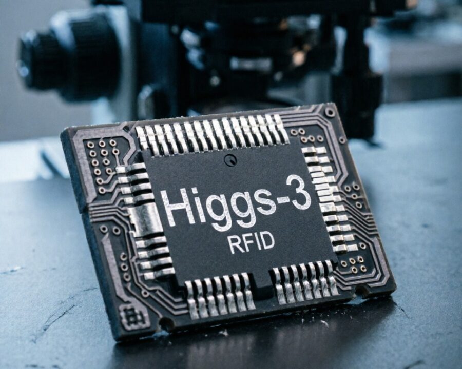
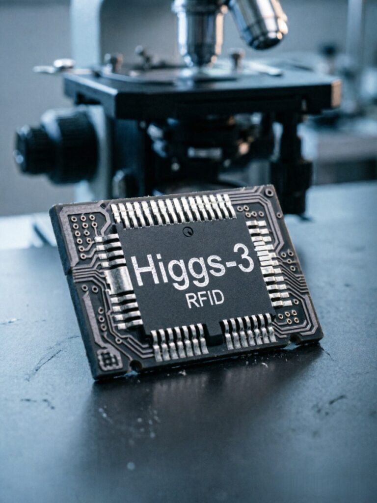
- Based on the Impinj R2000 platform;
- Support RSSI value detection;
- Adopt standard API interface, provide DEMO and source code, support VC, CS, JAVA, and other development routines;
Technology parameter | |
Working frequency | 902~928MHz(US);865~868 MHz(EU) |
Protocol | EPC C1 Gen2,ISO18000-6C |
| Main chip | Impinj R2000 |
RF power | 0~32dBm(adjustable) |
Reading distance | Up to 0~30m (Depend on antenna and environment ) |
Read rate | >700times/second |
Flash Power off save | 1Mbit (Power off save the data, customized) |
Time recording | Clock chip records card-reading time, customized |
Tag detection | Support RSSI value detection |
Communication parameters | |
RF interface | 32 SMA female connectors |
Baud rate(RS232) | 115200 bps (default ) |
Baud rate(TCP/IP) | 230400 bps (default) |
I/O interface | 2 way-road relay output,2 way -road I/O input |
Power parameter | |
Equipment power supply | DC 12V/3A |
Working power consumption | 10W(@Maximum output power 33dBm) |
Environmental parameters | |
Operating temperature | -20℃~55℃ |
storage temperature | -30℃~80℃ |
Storage humidity | 5%~95%RH No condensation |
Physical parameter | |
Size | 220X176X31mm |
Weight | About 2kg |
Material | Aluminum alloy |
I/O Interface definition
No | Name | Description |
1 | +12V | +12V output |
2 | GND | GND ground |
3 | IN1 | Optical isolation input 1 |
4 | IN2 | Optical isolation input 2 |
5 | NC1 | Relay 1 is always open |
6 | COM1 | Relay 1 common |
7 | NC2 | Relay 2 is normally open |
8 | COM2 | Relay 2 common |
As UHF RFID moves from pilot projects to enterprise‑wide infrastructure, the need to cover large areas, multiple zones, and complex environments with a single reader becomes critical. Enter the 32‑port UHF RFID fixed reader – a high‑density, multi‑antenna device that can drive up to 32 individual antennas from one compact enclosure. This class of reader is designed for warehouses with dozens of dock doors, retail floors with hundreds of inventory points, and industrial sites requiring blanket coverage without the cost and complexity of deploying dozens of separate readers. This comprehensive guide explores the architecture, performance, applications, and selection criteria for 32‑port UHF RFID fixed readers.
1. What Is a 32-Port UHF RFID Fixed Reader?
A 32‑port UHF RFID fixed reader is a professional‑grade RFID interrogator that integrates a powerful RF module (typically based on an Impinj E710, R2000, or similar chipset) with an internal multiplexer that switches the single RF transceiver across 32 antenna ports. Unlike a standard 4‑port reader that can connect to only four antennas, a 32‑port reader sequentially energizes each attached antenna, performing rapid inventory rounds across dozens of reading points.
These readers are not “32 independent readers in one box” – they share a single radio, so they cannot read from all 32 antennas simultaneously. Instead, they cycle through the ports in a user‑defined sequence, typically spending 10–200 milliseconds per antenna. The aggregate throughput (tags per second per zone) is slightly lower than using 32 separate 4‑port readers, but the cost, cabling, power consumption, and management overhead are dramatically reduced.
32‑port readers are used in applications where:
- Many physical points need RFID coverage (e.g., 30+ shelf sections or conveyor lanes).
- The read duty cycle per point is low (e.g., an inventory once per minute).
- Centralized processing and power are preferred over distributed readers.
2. Technical Architecture
2.1 Internal Block Diagram
A typical 32‑port fixed reader consists of:
- RF module – A high‑performance UHF RFID chip (Impinj E710, R2000, or equivalent) with adjustable power (0–33 dBm) and high sensitivity (–90 dBm or better).
- 32:1 solid‑state multiplexer – An array of RF switches (PIN diodes or GaAs) that route the transceiver’s transmit/receive path to one of 32 antenna ports. Insertion loss is typically 1–3 dB.
- Antenna connectors – Usually 32 × RP‑TNC or SMA female connectors on the rear panel.
- Application processor – Often an ARM Cortex‑A series running Linux, managing the multiplexer sequence, buffering tag reads, and handling network communication.
- GPIO and I/O – Opto‑isolated inputs (e.g., for 32 sensors) and relay outputs (for indicator lights or buzzers).
- Network interface – Gigabit Ethernet (often PoE+ for power), optional Wi‑Fi/4G.
2.2 Multiplexing Modes
Different applications require different antenna switching strategies:
- Round‑robin sequential – Ports are scanned in a fixed order (1,2,3,…32, then repeat). Simple and predictable.
- Triggered – A sensor connected to a specific GPIO input triggers the reader to read only the associated antenna port. This is efficient for conveyor lanes or dock doors where activity is intermittent.
- Adaptive skipping – The reader automatically skips ports with no tag activity for a configurable number of cycles, reducing total cycle time.
- Manual set – The user can program a custom sequence (e.g., read ports 1,5,9,13,… for an aisle‑by‑aisle inventory).
2.3 Multiplexer Insertion Loss and Power Compensation
Every RF switch introduces insertion loss – typically 0.5‑1.5 dB for a 32:1 multiplexer depending on quality. Additionally, cable runs from the reader to each antenna can vary in length. High‑end 32‑port readers offer per‑port power adjustment to compensate for these losses. For example, if port 1 has 2 dB of switch + cable loss and port 32 has 5 dB, you can increase the transmit power for port 32 by 3 dB (up to the regulatory limit). This ensures uniform read range across all zones.
3. Key Advantages of a 32‑Port Reader
| Advantage | Explanation |
|---|---|
| Cost efficiency | One 32‑port reader typically costs less than four 8‑port readers or eight 4‑port readers. Reduces hardware procurement, cabling, and installation labor. |
| Centralized management | A single IP address, one configuration file, one firmware update for 32 zones – simplifies IT and maintenance. |
| Lower power consumption | One reader with a multiplexer consumes less power than 32 separate 4‑port readers (e.g., 30 W vs. 500 W). |
| Space saving | One 1U or compact enclosure instead of multiple readers mounted across a facility. |
| Synchronized reading | Because only one radio is used, there is no risk of reader‑to‑reader interference – the reader cannot collide with itself. |
| Simplified triggering | GPIO inputs can be mapped directly to antennas; sensor triggers enforce read‑only when activity occurs. |
3.1 Trade‑Offs and Limitations
- Slower aggregate throughput – With 32 antennas, a full cycle might take 2–6 seconds (if 50–200 ms per antenna). Fast‑moving items may be missed if the antenna is not active at the exact moment of passage.
- Single point of failure – If the reader fails, all 32 zones lose RFID capability. Redundant readers or spare units are recommended.
- Insertion loss – The multiplexer reduces effective read range by 10‑30% compared to a direct‑connected reader. Use low‑loss multiplexers and higher‑gain antennas to compensate.
4. Typical Applications
4.1 Warehouse Racking and Bin Level Inventory
In a large distribution center with 20 aisles and 30 rack sections per aisle, a single 32‑port reader can be connected to 32 antennas, each illuminating a specific bay or set of shelves. The reader cycles through the antennas every 10 seconds, building a near‑real‑time map of inventory levels. When a forklift places a tagged pallet into a bay, the next inventory cycle detects the new tag. This eliminates manual cycle counts.
4.2 Multiple Dock Door Portals
A facility with 16 receiving and shipping doors can connect two antennas per door (one on each side) to a 32‑port reader – exactly 32 antennas. Each door is equipped with a photoelectric sensor connected to a GPIO input. When a truck backs into door #5, the sensor triggers the reader to switch to the two antennas for that door, perform a high‑speed inventory, and report tags. The other 31 doors remain idle, reducing unnecessary RF traffic.
4.3 Conveyor Sortation with Multiple Lanes
A high‑speed conveyor system with 16 parallel lanes can place one antenna over each lane. The 32‑port reader sequentially scans all lanes. As a carton passes under a lane’s antenna, its tag is read, and the sortation system diverts it accordingly. Because the reader cycles through all lanes every 500 ms (if set to 15 ms per antenna), the system can handle lane speeds up to 2 m/s.
4.4 Retail Shelves and Display Cases
In a large electronics retailer, each shelf segment or display case can be equipped with a small antenna. The 32‑port reader cycles through every shelf antenna, continuously monitoring which products are present. This enables real‑time out‑of‑stock alerts, planogram compliance verification, and theft detection – all from a single reader.
4.5 Library and Media Return Chutes
Libraries with multiple return bins (e.g., separate chutes for books, CDs, and DVDs) can place an antenna in each chute. A 32‑port reader monitors all chutes simultaneously. When a patron returns an item, the reader immediately updates the circulation database, without requiring staff to handle the item until the bin is full.
4.6 Asset Tracking in Tool Cribs and Lockers
A tool crib with 32 individual lockers or drawers can have one small antenna per compartment. The 32‑port reader checks each locker every few seconds. When a tool is removed, the system logs the transaction and can trigger an alarm if the removal is unauthorized. The central reader replaces 32 separate readers, saving cost and space.
5. Performance Characteristics
5.1 Antenna Switching Speed
The time required to switch from one antenna to another and settle the RF path varies:
- Solid‑state multiplexers (PIN diode) – Switching time < 10 µs, settling time ~100 µs. Negligible overhead.
- Electromechanical relays (rare in 32‑port readers) – 5‑10 ms switching time, not recommended for high‑speed cycling.
Most 32‑port readers use solid‑state designs and can achieve sub‑millisecond switching between ports. The dominant time is the inventory operation per antenna (typically 20–200 ms).
5.2 Total Cycle Time
Cycle time = sum of (per‑antenna inventory time) + switching overhead. For 32 antennas, if each antenna is read for 50 ms, total cycle time = 32 × 0.05 = 1.6 seconds. If you need faster updates, reduce per‑antenna time to 20 ms (0.64 seconds total). However, shorter inventory times may miss slow‑responding or weak tags.
5.3 Duty Cycle and Heat Dissipation
A 32‑port reader may operate with high duty cycle if scanning continuously. At an output power of +30 dBm, the RF module and multiplexer generate significant heat. Industrial 32‑port readers include active cooling (fans) or large heatsinks. Ensure the enclosure has adequate airflow if mounted in a cabinet.
5.4 Read Reliability
Because the radio is shared, a tag present at antenna #1 will only be read when that antenna is active. If the tag appears briefly (e.g., a carton moving past a portal) and the antenna is active for only 50 ms, there is a risk of missing the tag if the movement is faster than the dwell time. For high‑speed applications, use triggered mode (sensor‑activated) rather than continuous round‑robin scanning.
6. Selection Criteria for a 32‑Port UHF RFID Fixed Reader
6.1 RF Performance
- Output power per port – Up to +30 dBm or +33 dBm. Ensure per‑port power adjustment to compensate for cable/multiplexer loss.
- Receiver sensitivity – Below –85 dBm (preferably –90 dBm or better). Use the latest Impinj E710 chip for best sensitivity.
- Phase stability – Important for applications requiring angle‑of‑arrival or motion detection.
6.2 Multiplexer Specifications
- Insertion loss – Should be specified per port. Lower than 2 dB at 915 MHz is excellent.
- Isolation between ports – Minimum 30 dB to prevent leakage from one antenna to another.
- Return loss (VSWR) – Better than 15 dB (1.43:1) to minimise reflections.
- Hot‑switching capability – Can the multiplexer switch while the transmitter is active? Some require power to be reduced before switching.
6.3 Environmental and Mechanical
- Enclosure rating – IP50 for indoor rack-mount; IP54 or higher for industrial floor-mount.
- Temperature range – Typically –20°C to +55°C. For outdoor or freezer use, verify extended range.
- Connector type – RP‑TNC is common for UHF; ensure cabling matches.
6.4 Software and Integration
- API and control – LLRP (Low Level Reader Protocol) is standard for large deployments. Also look for RESTful interfaces, MQTT, and native SDKs for C#, Java, Python.
- GPIO mapping – Can you assign a specific GPIO input to trigger a specific antenna port? This is crucial for triggered modes.
- Firmware upgrade – Support for over‑the‑air (OTA) updates.
7. Installation Best Practices
7.1 Antenna Cabling
With 32 cables, cable management is critical. Use low‑loss coaxial cable (e.g., LMR‑240 or LMR‑400 for longer runs). Label each cable at both ends. Keep cable lengths as equal as possible to simplify power compensation. If lengths vary widely, measure loss per run and set per‑port power accordingly.
7.2 Antenna Placement and Overlap
Because the reader can only listen to one antenna at a time, avoid overlapping coverage where a tag could be within two antennas’ fields simultaneously – the tag may be read multiple times (once per antenna), which is harmless but wastes air time. For contiguous coverage (e.g., down an aisle), space antennas so their read zones just touch, with minimal overlap.
7.3 Power and Cooling
If using PoE+ (802.3at), ensure your network switch provides sufficient power for the reader’s peak draw (typically 25‑40 W). For non‑PoE models, use a dedicated 24 VDC supply. Mount the reader in a well‑ventilated area; if in a sealed cabinet, add cabinet fans.
7.4 Grounding and Surge Protection
For readers connected to outdoor antennas (e.g., yard gates), install lightning arrestors and ground the reader chassis. Use shielded Ethernet cables and ensure proper earth grounding.
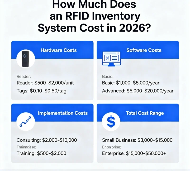
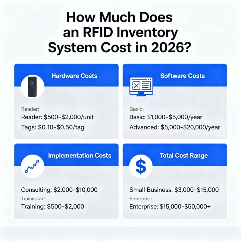
8. Cost Considerations and ROI
A 32‑port reader typically costs $3,000–$8,000 depending on brand and performance. By comparison, eight 4‑port readers would cost $8,000–$20,000, and 32 single‑port readers would be far more expensive. The 32‑port reader also reduces installation labor (one mounting, one network drop, one power connection) and long‑term maintenance.
ROI is realized through:
- Reduced hardware expenditure (50‑70% lower).
- Lower energy bills (fewer readers).
- Simplified software licensing (per‑reader licenses vs. per‑reader).
- Faster deployment (32 zones configured in one web interface).
9. Market Trends and Future Developments
9.1 Integration with Edge AI
Newer 32‑port readers include more powerful onboard processors (e.g., quad‑core ARM) running containerized applications. This allows them to perform tag filtering, direction analysis, and even anomaly detection without sending raw data to the cloud.
9.2 Higher Density (64‑port and beyond)
Some manufacturers offer 64‑port and 128‑port readers by cascading multiplexers. However, insertion loss grows with each additional stage. For extremely high density, distributed readers may be more practical.
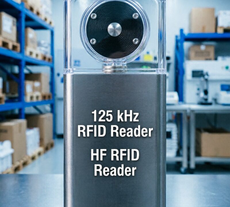
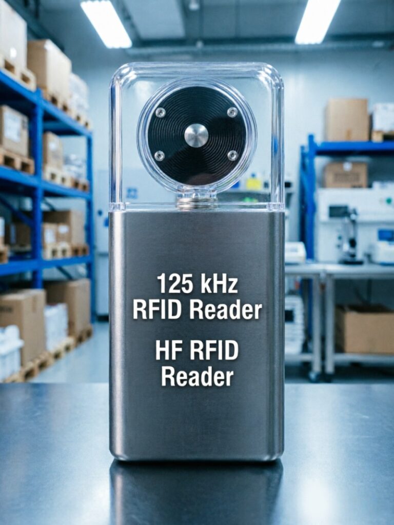
9.3 Hybrid UHF + HF
Emerging products combine 32‑port UHF switching with an integrated HF (13.56 MHz) reader for mixed tag environments – useful in libraries or retail where both UHF and NFC tags are used.
9.4 Wireless Antenna Switching
Experimental systems use wireless antenna modules (Bluetooth or UWB) that communicate back to a central reader, eliminating long coax runs. However, latency and power limitations remain challenges.
10. Conclusion
The 32‑port UHF RFID fixed reader is a powerful tool for large‑scale RFID deployments where coverage of many zones is required but budget, space, and management overhead are constraints. By integrating a high‑performance RF module with a fast, low‑loss multiplexer, these readers enable applications ranging from warehouse rack monitoring and multi‑lane sortation to retail shelf sensing and library return chutes.
When selecting a 32‑port reader, prioritize low insertion loss, per‑port power adjustment, triggered scanning modes, and robust software support. Proper installation – including balanced cable lengths, adequate cooling, and surge protection – ensures reliable operation for years. While not a replacement for dedicated readers in high‑speed or continuous‑read scenarios, the 32‑port architecture delivers unparalleled cost per reading point and centralised control, making it an essential component in the enterprise RFID toolbox. As the industry moves toward ever‑larger sensor networks, the 32‑port reader will remain a key enabler of scalable, affordable automated identification.